Simple Physics:
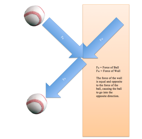
When it comes to building a bridge, the first concept that the builder must grasp is Newton’s Third Law of Motion, stating that every action creates an equal and opposite reaction. For example, if one were to throw a ball at a wall, the ball will exert a force onto the wall. However, if the ball does not go through the wall but bounces back into the thrower’s hand, then the ball was not thrown hard enough to break the wall, and the wall was able to exert an equal and opposite force onto the ball, causing the ball to go in the other direction. If the ball goes through the wall, however, then the wall was not strong enough to create an equal and opposite reaction and collapsed due to the overload of force. It is the balance of these two forces that is key to building a bridge.
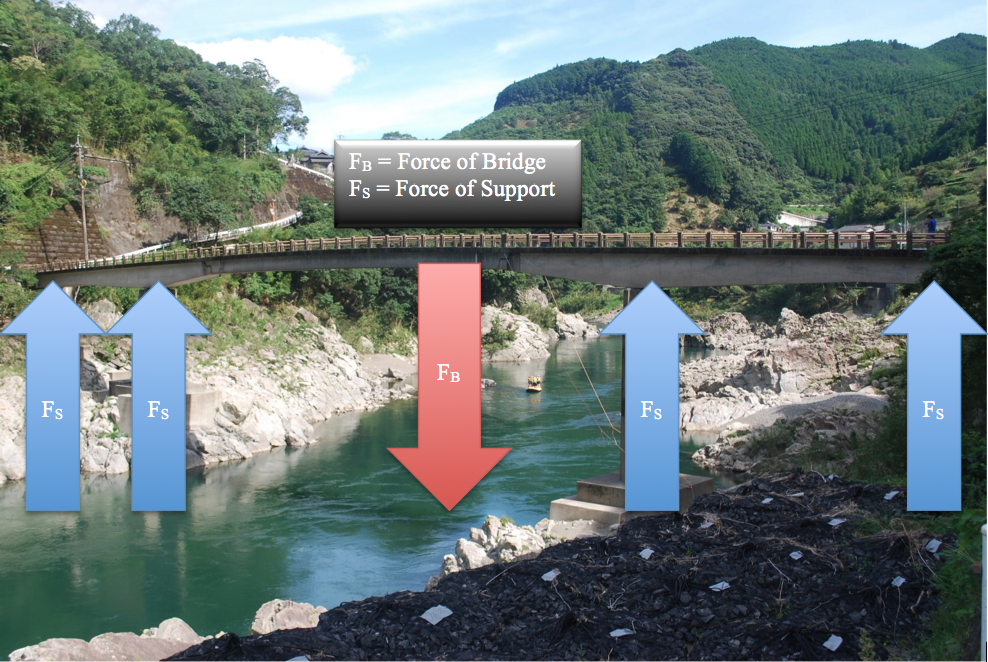
When building a simple beam bridge, one must take into consideration the weight of the roadway and the reaction of the support. As the weight pushes down onto the supports, assuming that the majority of the weight is being exerted within the center of the bridge, the supports must exert an equal and opposite reaction onto the weight so that the bridge will not collapse. In other words, think of the weight of the bridge being a weight (mg), and the supports being the normal force (FN) that acts against it. These two forces, which in this case are both in the “y” plane (vertically), must equal each other so the bridge does not collapse. When there are cars (ect) traveling on that bridge, however, the supports must exert a force that is much larger than the force of the bridge in order to keep the bridge from collapsing.
For example, say that the overall weight of a bridge is 500N (not including cars, buses, ect.), and the bridge will have four supports. The equation to find the amount of force that each support must exert on the bridge would be found like this:
FN – mg = 0
FB (Weight of bridge) + 4FS (force acting against weight) = 0
-500N (because this force is going downwards) + 4FS (because there are 4 supports) = 0
4FS = 500
FS = 125 N
This means that each support must exert a force of more than 125 N, so the bridge can hold its own weight and can hold cars, buses, ect. If you want the bridge to be able to hold 600 additional newtons of cars, buses, ect. then the equation would look like this:
-500-600N + 4FS = 0
4FS = 1100
FS = 275 N
This means that each support must exert an additional 150N onto the bridge if it wants to hold an extra 600N of weight.

All four FS’s need to be more than one FB
Of course, this is only a straightforward method for building a simple beam bridge. There are many different types of bridges that can be built, and so many ways to distribute the weight of the bridge so that it does not collapse.
Different Types:
There are four main factors used in describing a bridge:
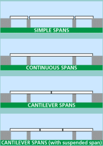
1. Span
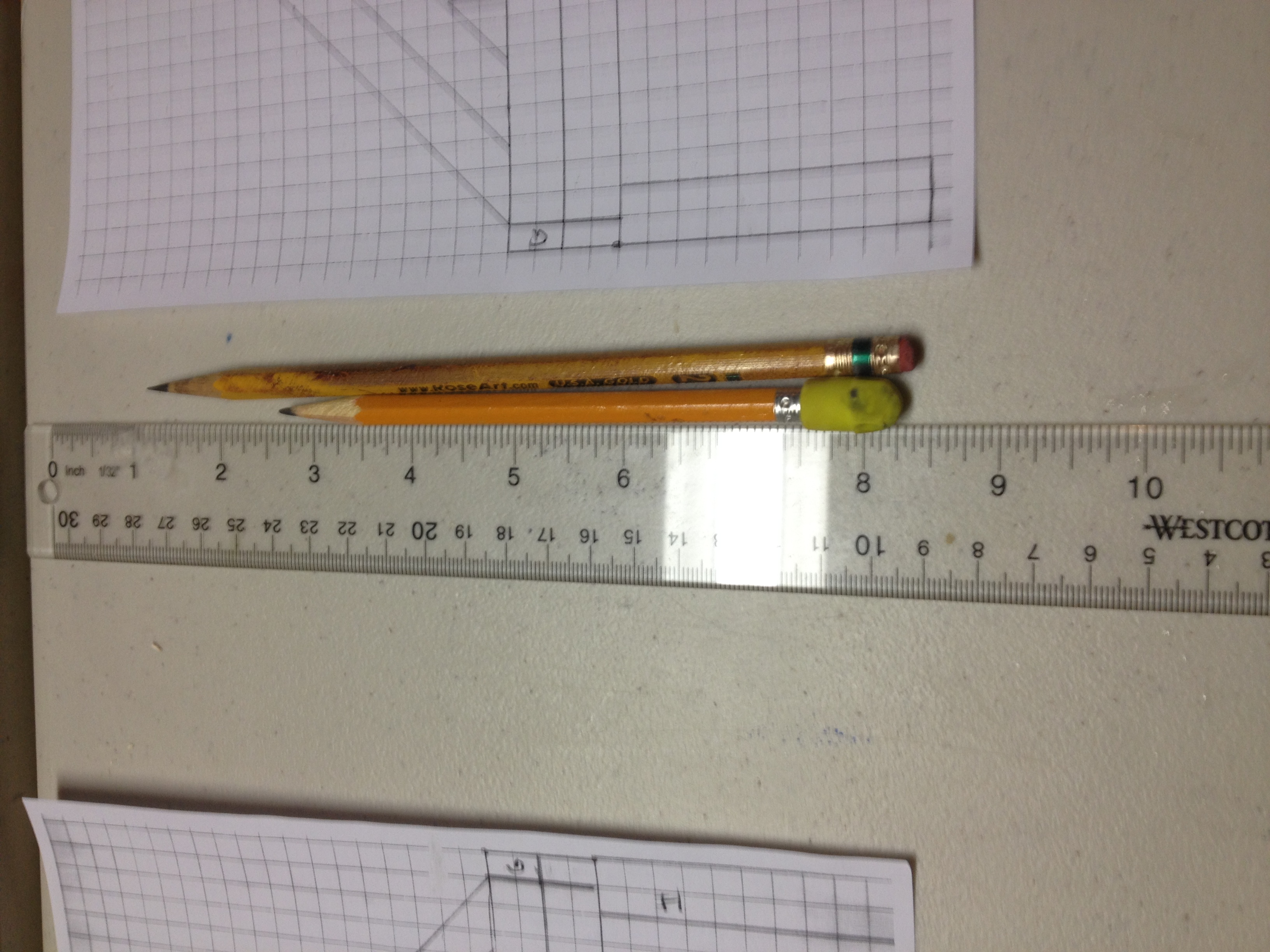
2. Material
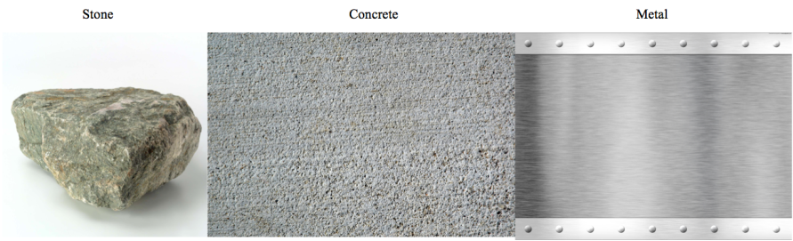 Some examples of materials are stone, concrete, and metal
3. Placement of the travel surface in relatio-n to the structure (Trusses)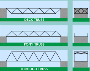
In a deck configuration (top), the structure is built underneath the road and is cross-braced on the bottom; in a pony configuration (middle), the road is built between two parallel trusses that are not connected at the top; in a through configuration, the road is built between two parallel trusses that are cross-braced above and below the bridge.
4. Form
The form of the bridge is the most important part of the construction, because the builder must find a way to distribute the weight of the bridge and people on the bridge using a truss or some other method.
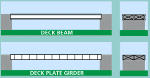
Beam/Girder:
A simple beam bridge, such as the one discussed earlier, would most likely be built using metal or reinforced concrete. Girder types are usually constructed using metal dividing the bridge into pieces, and are cross-braced between two beams.
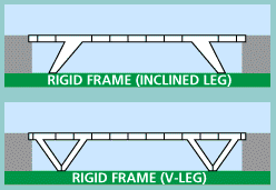
Many modern bridges use the rigid frame type, a design that integrates both a superstructure (a structure built on top of something else) and a substructure (an underlying or supporting structure). More often than not, the legs or the intersection of the legs and the road are one piece divided into sections.
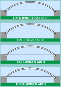
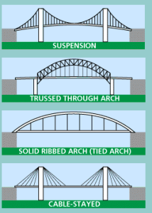
Arch Types:
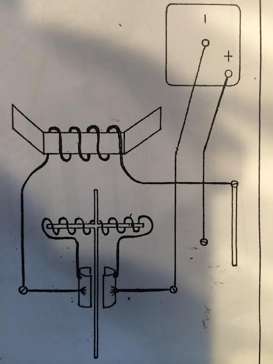
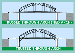
An arch bridge can be designed using the deck, pony, and through trusses, but must be built using hinges, allowing the structure to respond to various stresses and loads. (A through arch will be used to demonstrate):
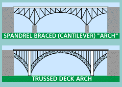
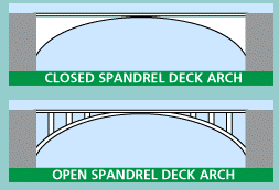
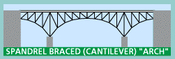
The configuration of the arch should also be put into consideration. Some common examples are solid-ribbed, brace-ribbed (or a truss arch), and spandrel-based. A solid-ribbed arch is normally constructed using curved girder sections. A brace-ribbed uses a curved through truss rising above the road. A spandrel-based arch (or open spandrel deck arch) holds the road on top of the arch. An arch bridge normally relies on vertical support to transmit the load, but some metal bridges that are spandrel-based are cantilever bridges, and rely on diagonal bracing for support.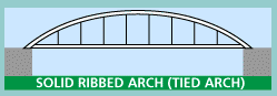
The “tied” or “bowstring” arch is normally used for suspension bridges, and the arch can be either trussed or solid. A tied arch holds its own weight by using the road itself as a tie piece.
The spandrel itself can be either closed or open, depending on the type of bridge and how much reinforcement it needs.
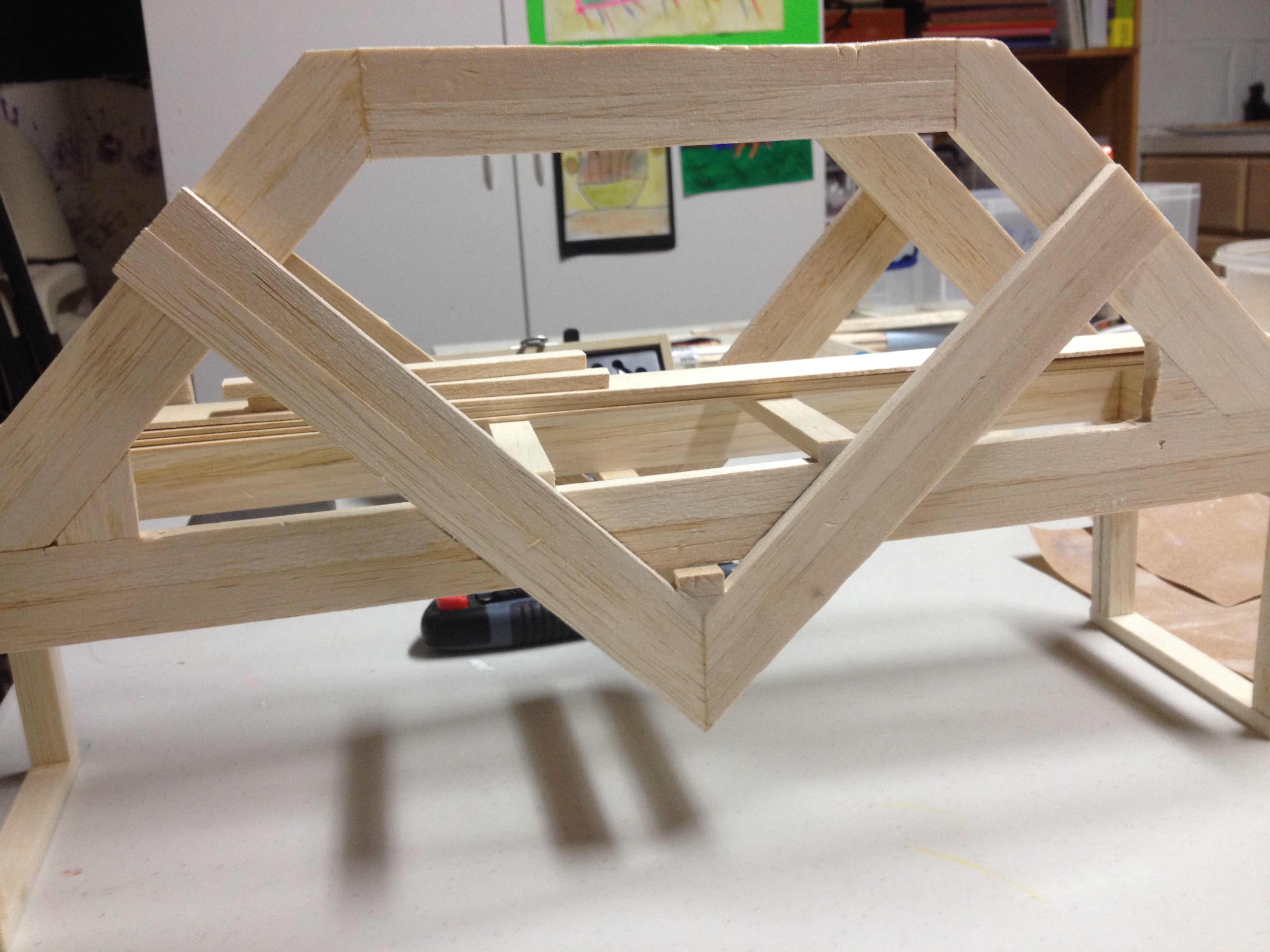
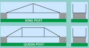
Simple Trusses:
A truss is a structure that is constructed using smaller parts. The simplest trusses are the king post truss and the queen post truss, though the latter is slightly more complicated and adds a horizontal top chord to increase its length (and the center is not as reinforced). As trusses evolved, the triangular shape began to be used more frequently, as the triangle is not easily deformed and its ability to balance stretching and compressive forces within the structure.
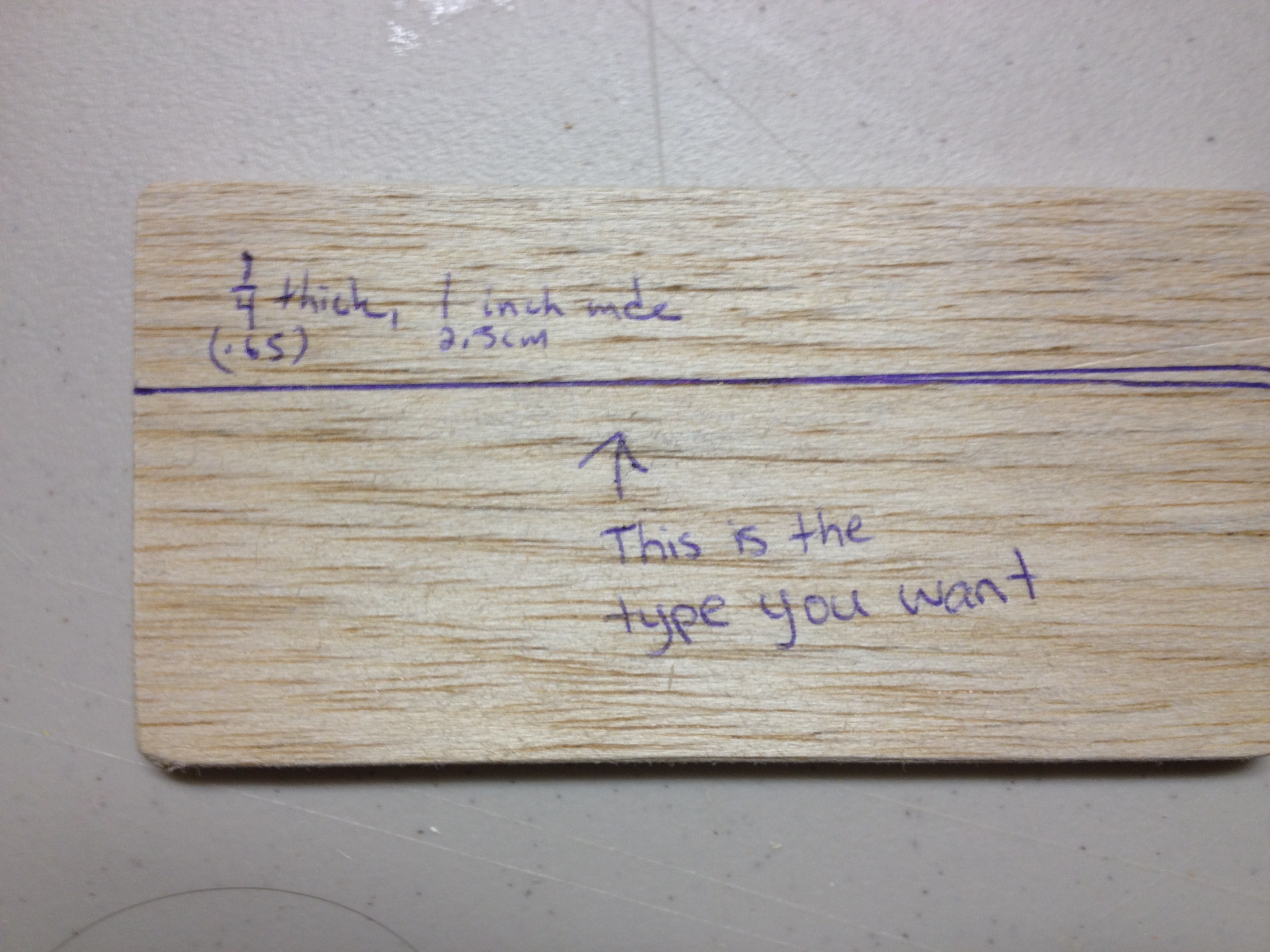
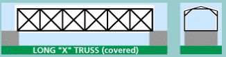
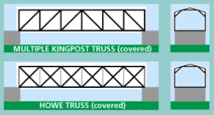
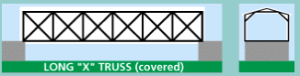
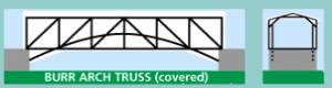
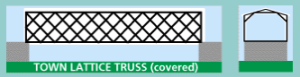
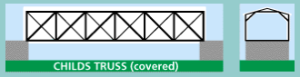
Covered Bridge Types (Trusses):
These bridges are typically made out of wood, with an enclosing roof protecting the timbers from damage and decay, therefore extending the life of the bridge. The most common trusses used to achieve this goal are the multiple king post truss, which expands upon the original king post truss shown earlier by adding symmetrical panels, and the Howe truss, which, in its simplest form, seems to be another expansion of the multiple king post truss. The long truss, developed by Stephen H. Long, and the Burr Arch Truss, developed by Theodore Burr, also expanded upon the king post and queen post designs.
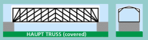
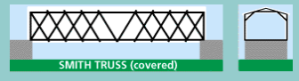
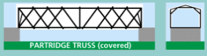
The town lattice truss, developed by Ithiel Town, used planks rather than the heavy timbers required to construct the king post and queen post designs, The Haupt truss, developed by Herman Haupt, concentrates the majority of its compressive forces through the end panels and onto the abutments at the end of the bridge. With the development of the Smith truss (designed by Robert Smith), the Partridge truss (designed by Reuben L. Partridge) and the Childs truss (developed by Horace Childs) were created.
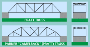
Pratt Variations of the Truss:
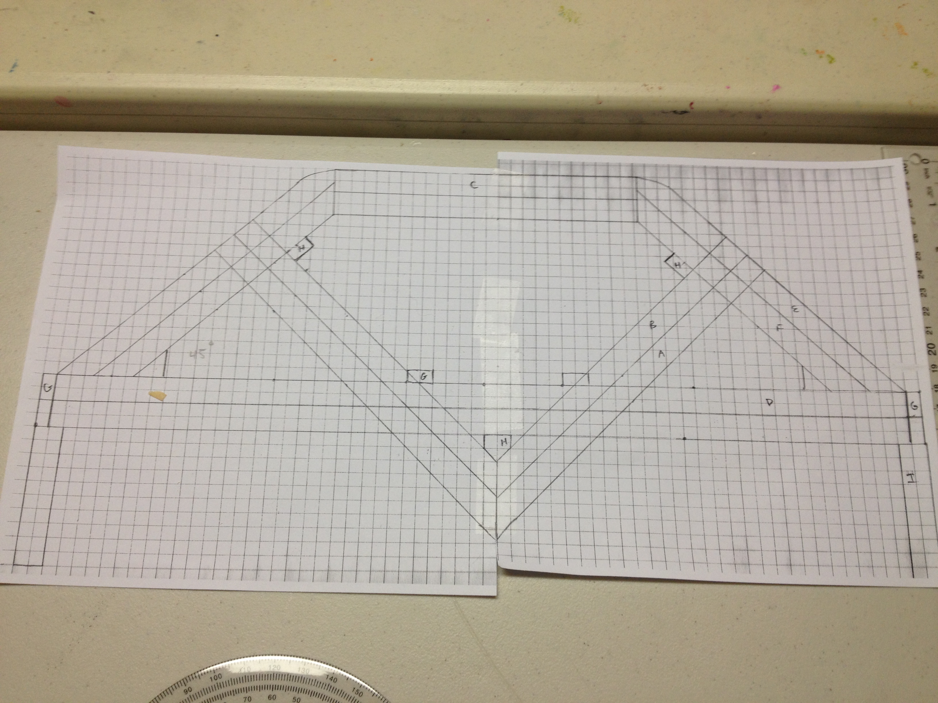
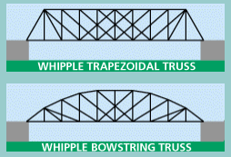
The Pratt truss, originally created by Thomas and Caleb Pratt, is a frequently-used truss that has many variations. To identify any type of Pratt truss, however, all one needs to do is find a diagonal web members that form a V-shape, and the center section has crossing diagonal members. One variation, created by Charles H. Parker, is a truss that has a top chord that does not remain parallel to the road, creating a lighter structure without losing its strength, allowing for more of the strength to be concentrated in the center and freeing the ends of extra load. The Whipple truss (developed by Squire Whipple), is a stronger version of the Pratt truss, with the diagonal tension spread across two panels rather than just one. It is most commonly build like a trapezoid, though bowstring versions were created as well.
Warren Variations of the Truss:
The Warren truss, developed by James Warren and Willoughby Monzoni, are usually built using many equilateral or isosceles triangles formed by the web members that connect the top of the bridge to the road. The triangles are often further subdivided.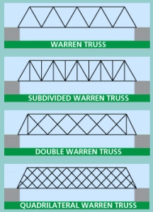
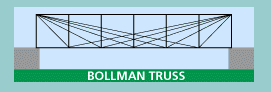
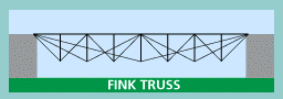
There are many other types of trusses that were used beyond those mentioned here, but they are not as commonplace as those listed. Some examples are the Bollman truss and the Fink truss.
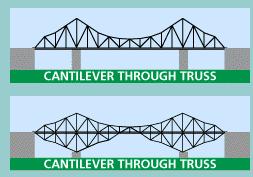
Cantilever Types:
Cantilevers are structural members that projects beyond its support and is only supported at one end, allowing the bridge to achieve greater spans than those of the same superstructure type. Some bridges that appear to be arch types are actually cantilever types, which can be identified by the diagonal braces used in the open spandrel. Pratt and Warren trusses are the most frequently used trusses for this type of bridge. The original cantilever uses a through truss extending above the deck, or above and below the deck.
Suspension Types:
The bridges that are suspension types or their cousin, the cable-stayed bridge, are the longest bridges in the world. The road is supported by suspenders of wire rope, eyebars, or other materials.
Sources:
http://ffden-2.phys.uaf.edu/212_spring2011.web.dir/Peter_Aumau/basic-physics.html
http://pghbridges.com/basics.htm (information and pictures)
http://www.mathsinthecity.com/sites/most-stable-shape-triangle
Apple Dictionary